
Chapter 2 Extended
...Continued
We continue from where we left off from chapter two of the book where we were discussing the orange.
Green Apple
This section covers the workflow for modeling and positioning the apple in the scene, following a process similar to the naval orange.
Note: This section repeats instructions on selecting Tools, inserting new subtools, subdivisions, DynaMesh, and ZRemesher. For clarity, refer back to the earlier sections in this chapter.
Modeling the Apple
Follow these instructions below to create the base mesh for the apple.
1.) Insert a Sphere3D object into the ZTool hosting the table and bowl scene.
2.) DynaMesh the apple at Resolution 128.
3.) Use the SnakeHook, Inflate, and Move brushes to shape the silhouette into an apple form.
Tip: The Move, SnakeHook, and Inflate brushes are ideal for shaping an object’s silhouette and form, especially for beginners.
Use a large Draw Size with the Move and SnakeHook brushes to avoid surface lumps.
To add volume, use the Inflate brush with a Z Intensity of 10 or lower and a large Draw Size for gradual buildup.
4.) Once the form is established, apply ZRemesher with a target polygon count of 3 to 5.
5.) Refine the shape as needed after remeshing.
6.) Use the ZModeler brush to QMesh the stem from the top of the apple. See Figure 2.18.
Find a vertex point at the center of the indented section at the top of the apple.
ZModeler brush > Point > Split > Click-drag the point to split into a circular topology loop.
Extrude the Split surface outwards to the length of the stem.
Flatten and realign the top polygons with masking and gizmo3D, or Clip brushes.
7.) Add edge loops along the stem using ZModeler with Edge Action set to Interactive. See Figure 2.18.
Hover the cursor over an edge on the long vertical poly loop of the stem.
ZModeler brush > Spacebar > Edge Action > Insert > Insert Multiple EdgeLoops > Turn Interactive Resolution and Elevation on.
Click-drag up to add a 3 or 4 edge loops, and lightly drag left to decrease the elevation, naturally tapering the stem’s shape.
Tip: Click and drag the target edge loop up or down to add or remove edge loops, and left or right to raise or lower the surface elevation.
8.) Smooth any hard lines on the top of the stem, then use the Inflate brush to gradually build volume and taper it for a more natural look.
9.) Subdivide the model using the Divide button until it reaches between 3 and 6 million polygons.
Tip: Press Ctrl/Cmd + D to quickly divide the model and add a new subdivision level.
10.) Lightly apply the SnakeHook brush with Alpha 08 to introduce subtle surface variation.
Tip: Adding an alpha to the SnakeHook brush lets you simultaneously move and texturize the surface. Light touch creates subtle, lumpy variations that break up smooth areas.
Figure 2.18 - Shows the results of steps 1 through 10.
Figure 2.18 - Shows the results of steps 1 through 10.
Duplicate and Position the Apples
With the Apple model complete, the following instructions cover duplicating and positioning it within the scene.
Note: These steps repeat earlier instructions on duplicating subtools, using Stager to store position stages, and transforming with Gizmo3D. Refer to previous sections for more details.
1.) Duplicate the apple a few times in the Subtool SubPalette.
2.) Store the Home Stage for each apple subtool.
3.) Use Gizmo3D to position the apples within or around the bowl.
4.) Store the Target Stage for each apple subtool.
Note: Adding more objects later will require you to reposition these apples. Once the Target Stage is stored, you can adjust its orientation anytime by keeping the Target Stage actively selected when applying transformations with Gizmo3D, Transpose Tool, and Transformation-based Deformation parameters.
Tip: When duplicating subtools, use folders to group them. Folders improve organization, allow you to toggle group visibility, and simultaneously apply Gizmo3D transformations to all subtools in the folder.
Figure 2.19 - Shows duplicate apple objects stored in a folder.
Grapes
This section covers the workflow for modeling and positioning the grapes in the scene, following a process like the one used for the apple and naval orange, while introducing new detailing and model instancing techniques.
Modeling the Grapes
The reference requires many grape instances, so we’ll first build a base mesh which later can be turned into InsertMesh brush for fast, precise placement.
Note: This section repeats instructions on selecting Tools, inserting new subtools, subdividing, DynaMesh, and ZRemesher. For clarity, refer back to the naval orange section in this chapter.
Follow these instructions below to model the grapes.
1.) Repeat the same steps used for modeling the apple and orange and create the shape to match the proportions of a grape.
Use sculpting brushes or create a VDM brush to sculpt small bumps or imperfections where the stem attaches at the top of the grape.
ZRemesh the model with the default settings to create a clean topological base mesh.
2.) Insert a new cylinder into the scene and sculpt a grape stem.
Use DynaMesh, Move, and ClayBuildUp brushes to reshape the cylinder into a grape stem.
Use Gizmo3D to position the step at the top of the grape.
ZRemesh the stem with the default settings model to create a clean topological base mesh.
Note: We will use the stem created in step 3 to connect to the grape stalk created in the next section.
3.) Merge the grape and stem subtools into one.
Place the stem subtool above the grape subtool, or vice versa.
Tool palette > Subtool > Merge down.
Tip: Before merging subtools, remove existing subdivisions from all subtools. Merging a subtool with subdivisions will collapse it to its current level, losing all others.
4.) Subdivide the grape a few times to increase resolution for sculpting finer details.
5.) Apply any final sculptural details to the grape and stem, using either sculpting brushes, VDM brushes, and Surface noise as desired.
6.) Once the grape is complete, create a new folder to organize the grape and stalk objects.
Figure 2.20 - The results of steps 1 through 7 to create the grape base mesh.
Modeling the Grape Stalk
To create the grape stalk, we’ll use ZSpheres, which lets you quickly assemble a base structure by connecting simple spheres in a chain-like hierarchy. ZSpheres offer the flexibility needed to build branching, organic forms that don’t conform to standard primitives. After creating the stalk’s base with ZSpheres, we’ll use an InsertMesh brush and MeshFusion to efficiently add and fuse additional branches. MeshFusion allows you to merge InsertMesh geometry directly into a surface by generating new topology at the connection point.
Follow these instructions below to create the grape stalk.
1.) Use ZSpheres to build the base structure of the grape stalk.
SubTool SubPalette > Insert > Click ZSphere to add it into the existing scene as a new subtool.
Activate Draw mode in the top left of the canvas and click-drag on a ZSphere to add a connected ZSphere.
Tip: Drag while holding Shift to set the new ZSphere to the same size as the connected ZSphere.
Activate Move, Scale, or Rotate modes in the top left of the canvas and click-drag a ZSphere to apply their respective transformations. Use these modes to shape, form, and create the grape stalk branches.
While in Draw mode, Alt/Option-click a ZSphere to delete it.
2.) Activate Preview mode to simulate the resulting topology and create a new PolyMesh3D object.
Press A on the keyboard to activate Preview mode for ZSpheres, viewing the resulting topology.
When satisfied with the result, click Make PolyMesh3D in the Tool palette to convert it to a sculpt-able mesh.
Select the Tool with all of our objects for the scene.
Insert or Append the PolyMesh3D stalk object into our scene Tool.
Note: ZSpheres Preview mode is found under Tool > Adaptive Skin. When active, click Make Adaptive Skin to convert the preview into a sculpt-able mesh, which works like Make PolyMesh3D.
Tip: Adaptive Skin uses two topology modes: Density and DynaMesh. By default, both are active, generating a DynaMesh at a resolution of 256 with a Density of 2. To disable DynaMesh, set its resolution to 0. For this exercise, keep the default settings.
3.) Use the Inflate and SnakeHook brushes to break up any stiffness in the mesh and taper areas along the grape stalk for a more natural form.
4.) Create an IMM brush for a small branch to use as an InsertMesh to expand the branch stalks quickly.
Note: Step 4 describes creating an InsertMesh with a single hole in its geometry, which is required later for the MeshFusion technique. MeshFusion only works when the InsertMesh has one hole at the end. See Figure 2.20 for an example.
Duplicate the branch subtool.
Rotate the model to view it from a precise angle to capture a clean selection around the target brand.
Ctrl/Cmd+Shift-drag to draw a selection around a small branch.
Tip: Ctrl/Cmd+Shift-drag draws a green selection that hides all other model parts except for the selection. Ctrl/Cmd+Alt/Option+Shift-drag draws a red selection, which hides the part of the model within the selection. Take a moment to navigate the branch and hide excess geometry to create a clean, open hole at the branch’s end, similar to the top of an opened soup can.
Tool palette > Geometry > Modify Topology > Click Delete Hidden.
Note: To ensure MeshFusion works in later steps, you must delete all hidden geometry. Hiding it is not enough for the process to function correctly.
Ctrl/Cmd+W to create a single Polygroup for the small branch.
Rotate the branch so the tip points toward the screen, and the open end faces away from the camera.
Note: This orientation determines how the InsertMesh will draw from the surface in the following steps.
Press B and select Create InsertMesh.
Click New.
5.) Apply the InsertMesh process for MeshFusion.
Select the PolyMesh3D version of the stalk subtool.
Tip: Users often confuse the ZSphere armature in Preview mode with the resulting PolyMesh3D. After converting to PolyMesh3D, move the ZSphere subtool to a folder or exit Preview mode to avoid confusion.
Ctrl/Cmd+W to Polygroup the model as a single Polygroup.
Rotate and zoom the model to a branch section to add the InsertMesh.
Ctrl/Cmd-draw a small mask equivalent to the InsertMesh object’s hole size.
Ctrl/Cmd+W to Polygroup the masked area.
Drag to draw the InsertMesh branch within the new Polygroup area.
Activate Gizmo3D and move the insert mesh away from the surface so it’s not touching it.
Click Draw mode on the top left of the canvas before moving to the next step.
6.) Apply MeshFusion to weld the surfaces together.
Ctrl/Cmd-drag to clear the mask from the InsertMesh operation.
Ctrl/Cmd-drag again to apply MeshFusion, welding the gap between the objects with new topology.
7.) Repeat the InsertMesh and MeshFusion process to develop the grape stalk fully.
To recap, MeshFusion simplifies branch creation compared to manually building each one with ZSpheres. Once the base structure is in place, use InsertMesh with MeshFusion to attach branches and automatically generate connecting topology, making the workflow faster and more adaptable.
Populating the Grapes
With the grape base mesh created, we’ll use the InsertMesh brush system to populate the grapes on the stalk branches.
Note: This section repeats instructions for creating and applying InsertMesh brushes. For clarity, refer back to the grape stalk section.
Follow these steps below to create and populate the grapes.
1.) Create an InsertMesh brush from the grape.
Align the grape so the stem faces the screen and the bottom points away.
Set the Grape to a subdivision level with strong details, but not too high.
Tip: Set the Active Points count to your desired level before capturing the InsertMesh brush. Avoid using high poly meshes repeatedly, as this can slow down performance. For reference, the example grape has about 19,000 polygons.
2.) Repeatedly click-drag the InsertMesh grapes on the stalk branch tips to place the grapes.
Tip: Monitor your polycount as you place grapes with the InsertMesh brush. After inserting a dozen grapes notice your polygroups, use these to manage the grapes in clusters. This alows you to separate the items into separate subtools to help keep the polycount of each subtool low. The InsertMesh brush system groups them to the grape stalk subtool. To split your subtools, use selection brushes to Ctrl/Cmd+Shift-click the grape stalk to isolate it, reverse the selection with Ctrl/Cmd+Shift-click on the canvas, then use Split Hidden from the Subtool palette to separate the grapes into smaller groups.
Organize and Reposition the Grapes
The final step is to group all the grape and stalk subtools into a folder and reposition them in the scene. Use the Folder system, which allows you to move all contained objects together with the Transpose Set function, which activates Gizmo3D and selects the objects in the folder.
Follow these steps to organize and reposition the grapes and the stalk.
1.) Place the grapes and stalk subtools into a single folder.
2.) Subtool palette > Select the Folder Gear icon > Transpose Set
3.) Use Gizmo3D, activated in the previous step, to move and rotate the grapes into the scene on the table.
After adjusting, exit Gizmo3D mode by clicking Draw mode.
Figure 2.21 - The process and results for the stalk and grapes.
To recap, we used a combination of ZBrush tools to sculpt and populate the grapes in our scene. The workflows you’ve practiced here are not just for grapes; you can carry their versatile techniques into countless future modeling projects.
Bananas
Overview
This section focuses on constructing both a single banana and a full banana bunch using foundational modeling techniques. You’ll use ZModeler, ZRemesher, and deformation tools to refine shape, bridge geometry, and apply VDM surface details in a clean, organized workflow.
Instructions
1.) Sculpting the Single Banana
Start with a cylinder as your base primitive.
Use symmetry along the vertical axis and carve in the form to block out the banana’s shape from end to end. TrimDynamic is a good brush for this surface type.
Use the Gizmo Bend Deformer to bend the banana into a natural curve.
Tip: Focus on gesture first before refining silhouette and proportions.
Note: Subtle flattening of the form should be done progressively. Run ZRemesher multiple times as you refine to maintain clean topology.
2.) Adding surface texture and stem tearing
Subdivide the banana to several million polygons.
Begin applying VDM textures for subtle surface variation.
Activate AccuCurve under Curve settings and use the SnakeHook Brush to pull and taper the torn stem for a frayed appearance.
Tip: Repeat the tear gesture with varied angles for more natural effects.
Note: Don’t forget to turn off AccuCurve when finished to avoid unintended results.
3.) Creating the Banana Bunch
Delete the banana’s subdivision levels to enable polygon-level edits.
Hold Ctrl and use the Gizmo to duplicate bananas and reposition them so the tops meet.
Delete the end caps of each banana to prepare for welding.
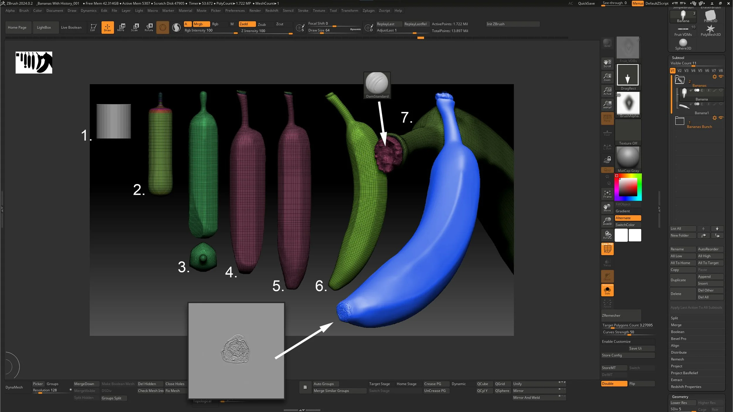
Fig. 2.22 – Shows where I begin and end with creating my banana. Step 1 begins with a single banana and proceeds through duplication and positioning.
4. ) Bridging the Bananas Together
Use the ZModeler Brush > Bridge feature to connect the open caps between bananas.
Continue until all bananas are bridged together, leaving a large open cap on top.
Use Tool > Geometry > Modify Mesh > Close Holes to seal the final top opening.
Tip: Work in a circular pattern when bridging multiple bananas to avoid misalignments.
Note: This approach maintains individual banana definition—unlike Dynamesh, which would undesirably merge everything together.
5.) Finalizing and Detailing the Bunch
Run ZRemesher on the unified bunch mesh (target: 5–7).
Subdivide to the low millions and use Trim Dynamic to sculpt chopped marks at the top of the bunch (as if cut with a machete).
Apply your VDM brush for texture refinement across the surface.
Fig. 2.23 – Shows the evolution of the banana as a bunch. The approach requires extensive use of the ZModeler brush.
Why didn’t we just Dynamesh them all together? If we had Dynamesh our banana bunch, we would have had to deal with the bananas fusing together.
Now subdivide your model to the low millions of polygons. Select your trim dynamics brush and carve into the model. Notice that the marks on the top are the result of them being chopped with a shape knife or machete. Keep this in mind as you shape your banana bunch top. Once the shape is achieved, I apply the texture from my VDM brush.
Strawberry
Overview
Strawberries have a uniquely textured surface that can be intimidating to sculpt, especially for beginners. Their noisy skin, delicate leaves, and small embedded seeds require careful handling in ZBrush. This section will guide you through an efficient and practical method to build a believable strawberry model using VDMs, cloth simulation, and radial symmetry—all while maintaining clean workflow and scene organization.
1. ) Start with the Fruit Base
Begin with a sphere and use the SnakeHook Brush (with Y symmetry active) to pull it into a strawberry-like shape as if standing balanced on its apex. Once satisfied with the form, ZRemesh the model to a resolution of 3–5 for cleaner topology.
2.) Organize and Prepare
Place the sculpted fruit into a new Subtool folder labeled “Strawberry” and set it aside. This will be important for keeping grouped duplicates later.
This helps when moving and scaling multiple objects at the same time.
3.) Create the VDM Seed
On a separate subtool, Insert a VDM Plane into your scene and sculpt a single seed using Clay Buildup and Dam Standard, with symmetry enabled. This becomes the basis for quickly populating the surface later.
4.) Build the Leaves
Insert a plane into the strawberry folder and subdivide it into the 100,000s.
Mask a radial silhouette of the leaves and extract the mesh via Tool > Subtool > Extract with 0 thickness and Double Sided OFF.
Position the extracted leaves atop the strawberry.
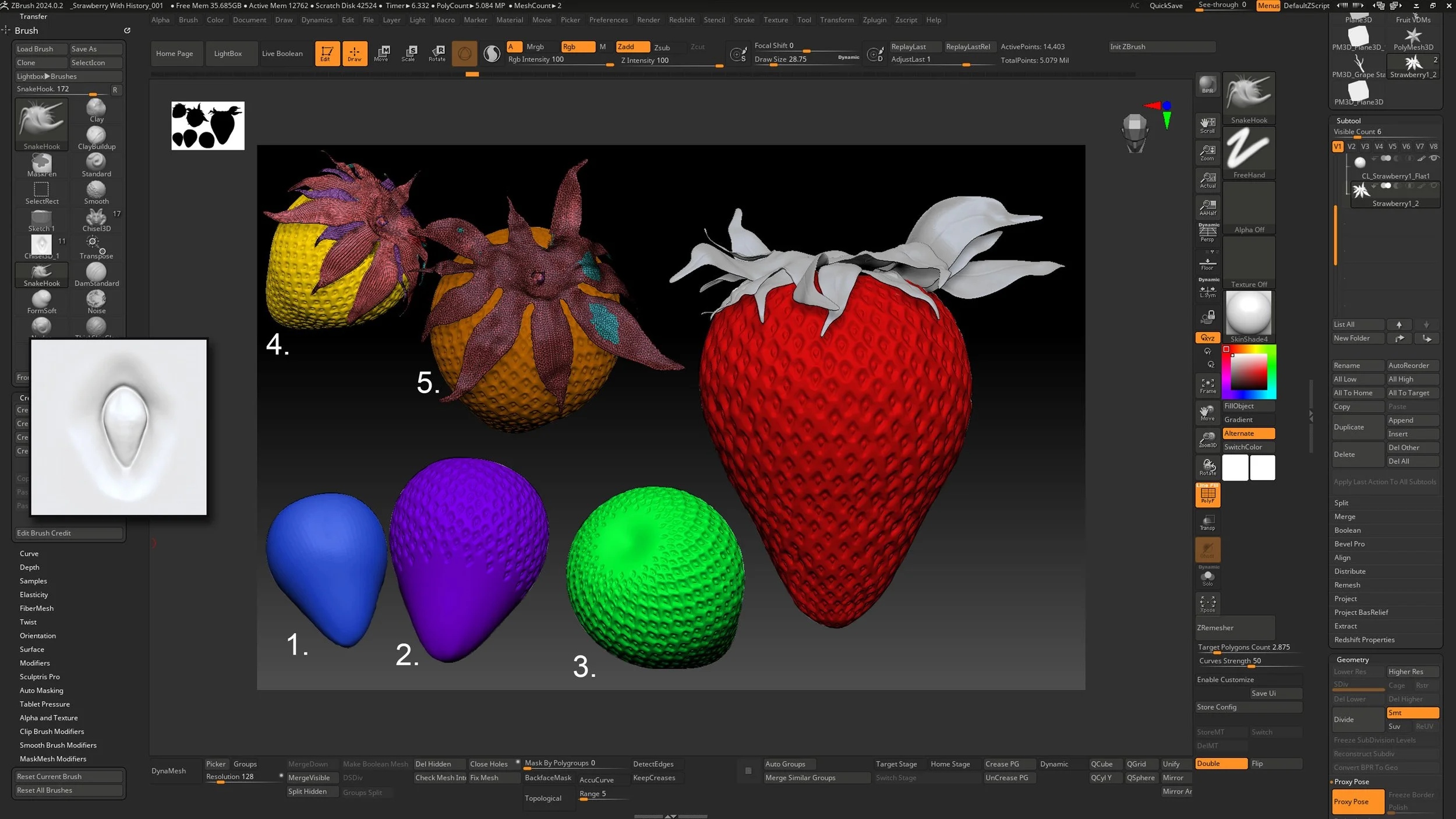
Fig 2.24 Radial symmetry used with VDM brushes can quickly populate the surface saving much time. Be careful not to push for too much perfection.
Tip: Utilize the curve mode found in Brushes > Curves > AccuCurve for a sharper falloff effect with the SnakeHook Brush.
5.) Simulate Cloth Dynamics.
Run a cloth simulation to allow the leaves to fall naturally onto the surface. Then, using the Anchor Brush, gently twist and peel the leaves outward to achieve a natural look.
Keep your dynamic settings standard for the most part.
The higher the polycount, the lower the simulation will be.
Try just using the cloth brushes, i.e.: ClothHook, ClothNudge, ClothPull, and ClothWind, as another option for treating the leaves.
6.) Detail the Strawberry Surface
Subdivide the fruit up to 5–9 million polygons.
Activate symmetry and radial symmetry in the Y-axis, set to 15–18.
Use the VDM brush to apply seeds in staggered rows from top to bottom.
Introduce subtle irregularities with additional brushes (e.g., SnakeHook or ClayBuildup) to avoid a “machine-made” appearance.
7.) Duplicate as Needed
When populating your scene with more strawberries, duplicate the entire strawberry folder, not just the individual subtools, to maintain structure and grouping.
Tip: Use radial symmetry to dramatically speed up repetitive detailing like seed placement. Aim for staggered rows to mimic the natural pattern found on real strawberries.
Note: Avoid over-polishing the surface. Too much perfection can make the model appear artificial. Imperfections bring character and authenticity to your work.
Melted Candle Stick
Overview
This sculpt begins with a simple cylinder but evolves into a layered and expressive candle with a melted wax story. You’ll learn to handle polygroups, creasing, handle construction with torus deformations, and organic wax creation using extraction and brush-based sculpting. The final result adds narrative, atmosphere, and visual storytelling to your still life.
Instructions
1.) Blocking the Candle and Wick
Start with a primitive cylinder to form the candle base.
Assign polygroups to the cylinder caps.
Use Crease PG to preserve edges, then ZRemesh the model with symmetry and “Detect Edges” enabled.
Use ZModeler > QMesh to extrude the wick upward from the center.
Continue refining the base and build the candle holder stem directly from the same mesh.
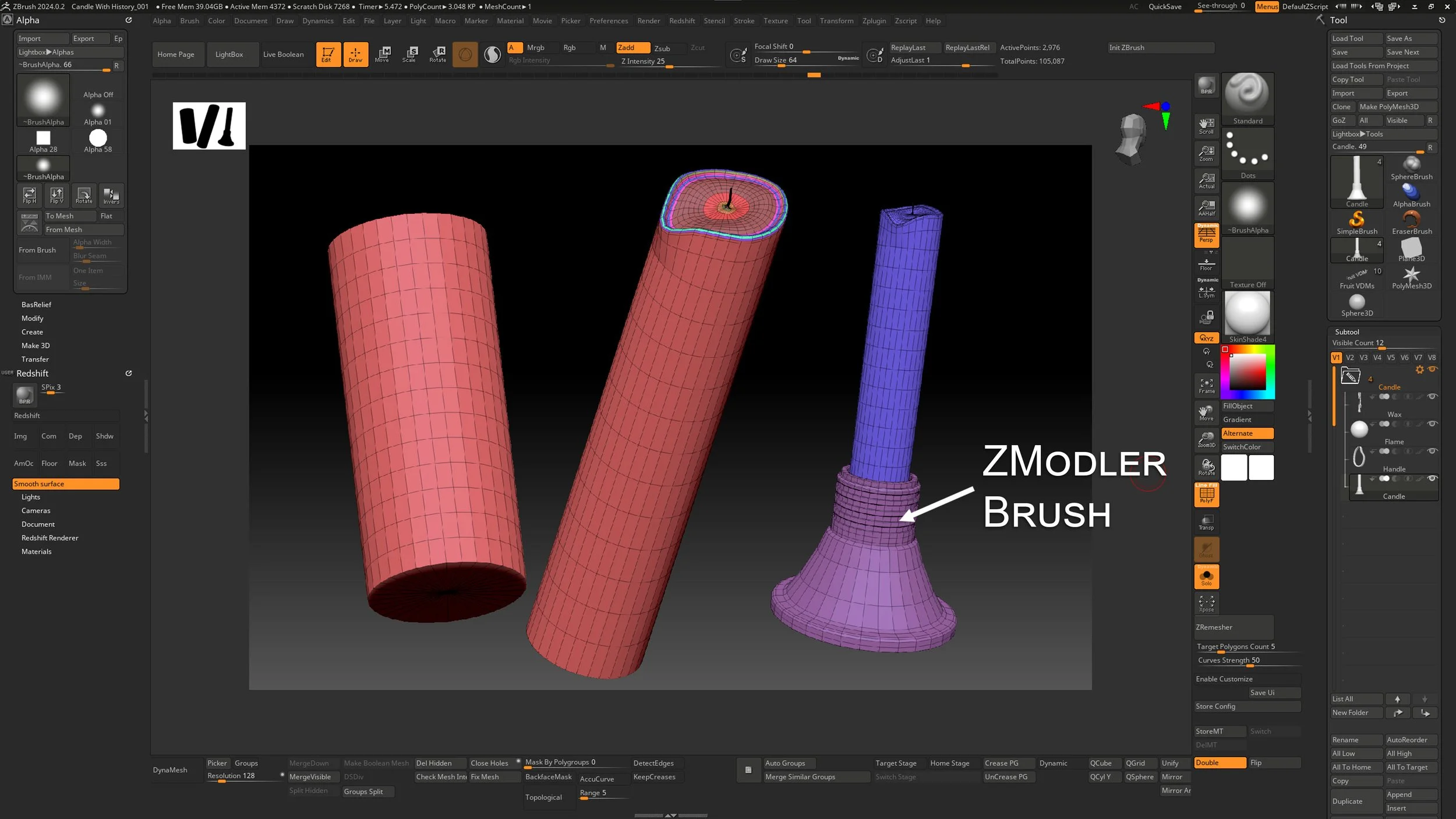
Fig. 2.25 – Illustrates the progression of the candle creation using simple primitives.
2.) Sculpting the Handle
See fig 2.26. Insert a torus into the candle folder.
Deflate the torus using the Inflate slider (negative direction).
Activate symmetry and use the SnakeHook Brush to bend the torus into a candle handle shape.
Add mechanical detail using the standard IMM brushes (e.g., screw attachments).
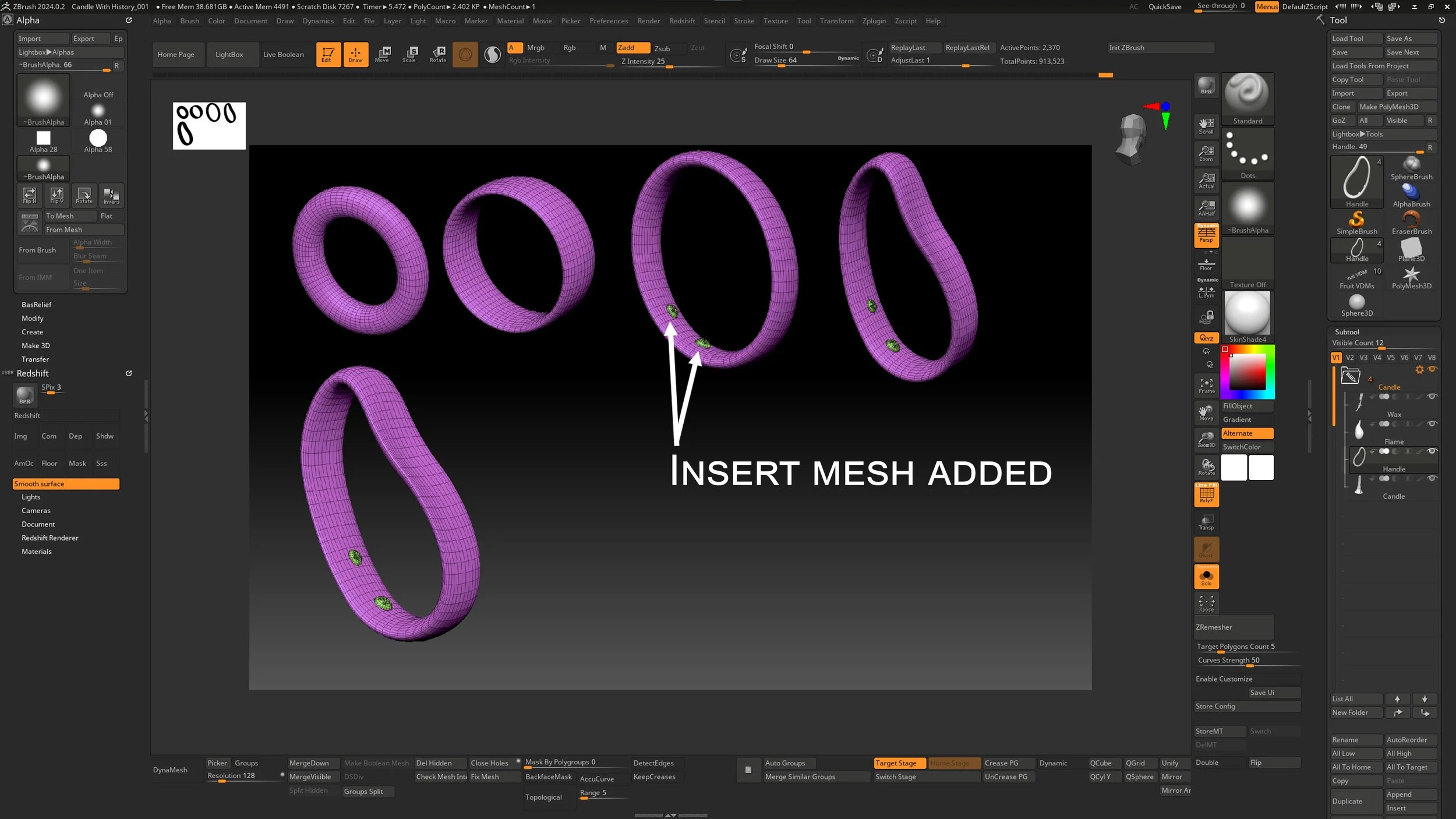
Fig. 2.26 – ZBrush gives me the flexibility to easily bend the form.
3.) Optional Flame Creation
Create a flame using a sphere.
Enable AccuCurve under Curve settings and pull flame tips with the SnakeHook Brush for stylized silhouette.
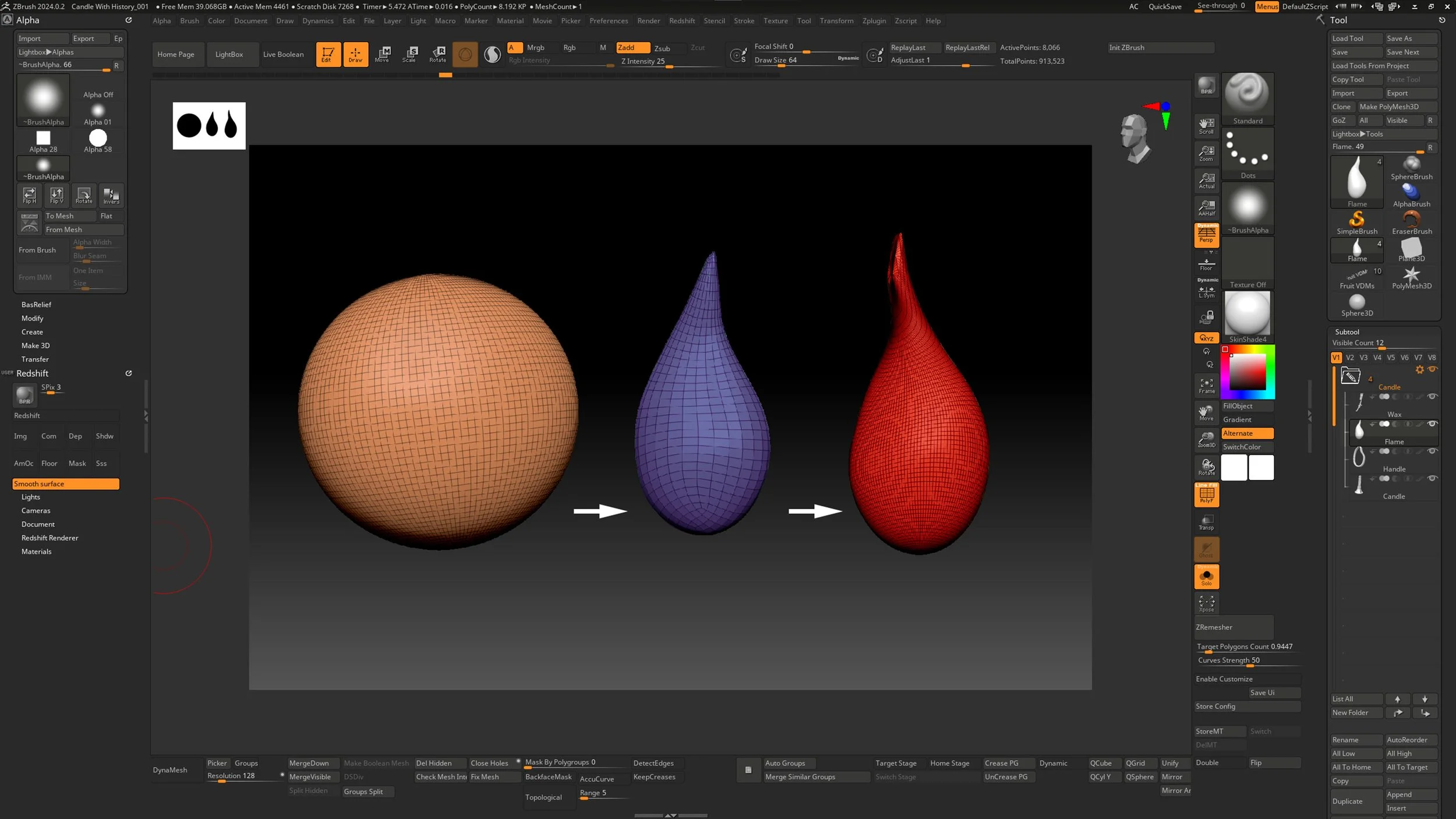
Fig. 2.27 – Using the SnakeHook Brush with AccuCurve to shape a flame silhouette.
Tip: Even if you don’t plan to use a flame, having it modeled gives flexibility for later design changes.
Note: AccuCurve can create sharp, expressive forms—great for organic effects like flames, but toggle it off after use.
4.) Sculpting the Melted Wax
Mask directly onto the candle mesh to define areas for wax buildup.
Use Tool > Subtool > Extract with low thickness and Double Sided OFF to generate the melted wax mesh.
Apply Dynamesh at a mid-to-high resolution.
Sculpt wax flow with Clay Buildup, define details with Dam Standard, and taper forms using the Directional Smooth Brush.
Add weight and realism by gently applying the Inflate Brush to simulate gravity’s effect on melted wax.
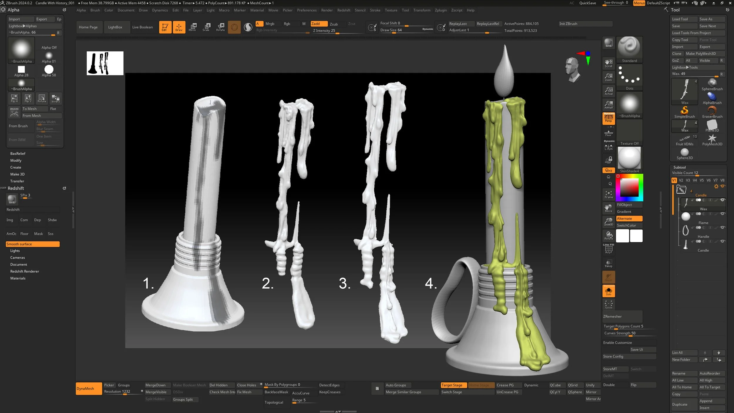
Fig. 2.28 – Wax detail should be left for final detailing. Using an extraction method from a mask, a quick result can be accomplished.
Tip: Use varied brush pressure and direction to simulate natural wax dripping.
Note: Wax contributes not just form, but narrative—reinforcing the idea of time and moment frozen in your still life.
Lemons
Overview description....
Follow these instructions below to create the strawberries.
1.) Provide instructions...
Tip: Insert tip regarding a specific step or set of steps.
Note: Provide a note related to parameters or special instructions that require expansion.
Again, pushing for a silhouette the lemon is created in a few quick steps. Much like the orange, the lemon was generated following the same steps. The process is quick to run through and provides great results overall. For a more in-depth rundown of the steps used, please refer to the coverage of the orange found earlier in the chapter.
Just to recap a few points, working in your details is best executed with subtlety. Even though an object like a lemon is a simple object, there is still a world of opportunity to celebrate. If you find the orange example to be kind of a basic goal, to mix things up, try and add some other irregularities, pathogens or imperfections to your lemon and extend your challenge.
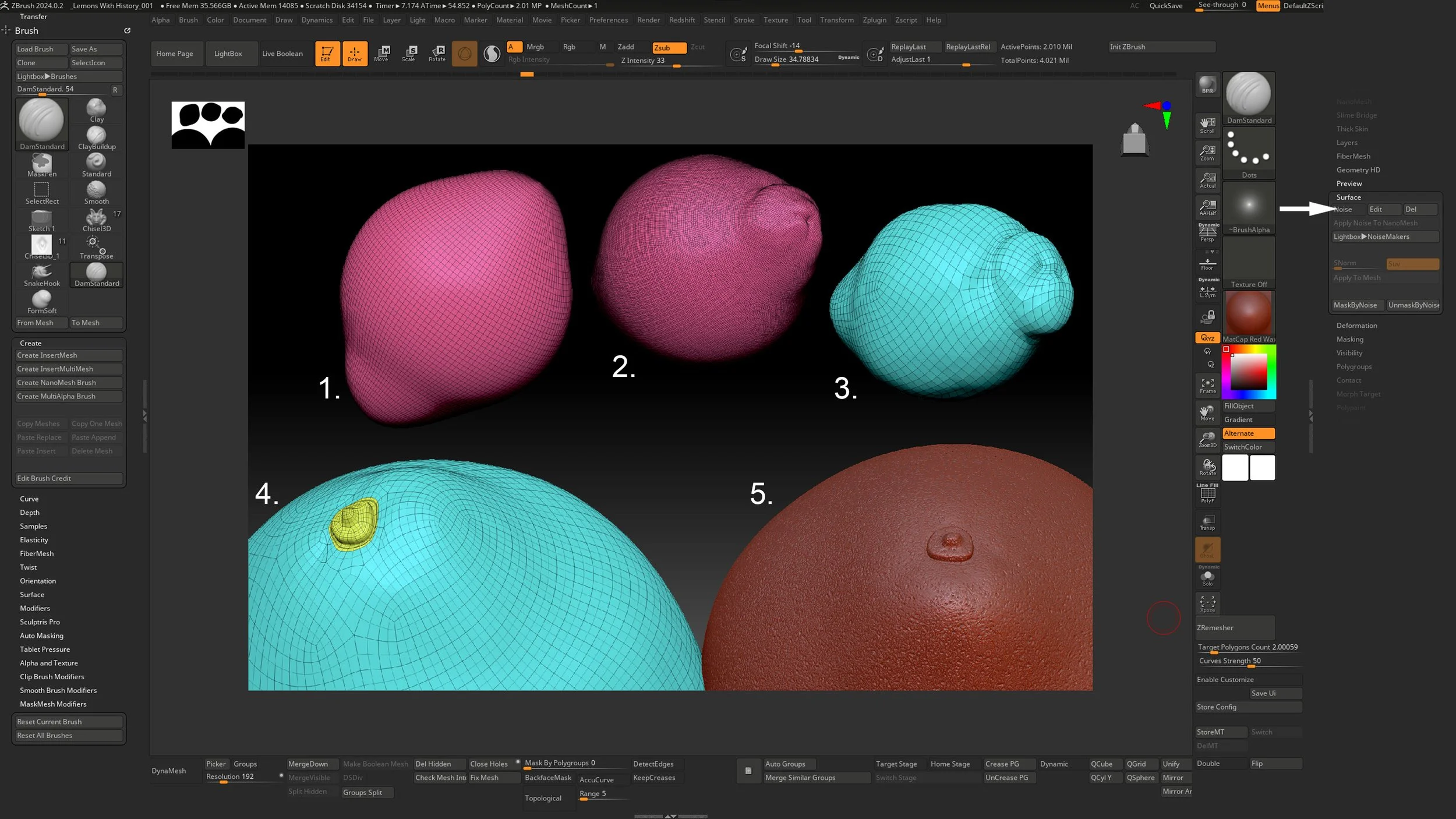
Fig 2.29 - From step 1 – 5 the basic shaper is created. The stem is created with the ZRemesher Brush
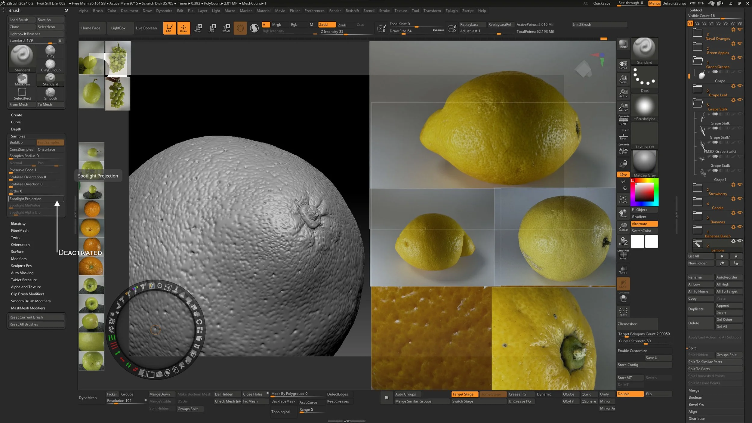
Fig 2.30 Lemon Surface progress
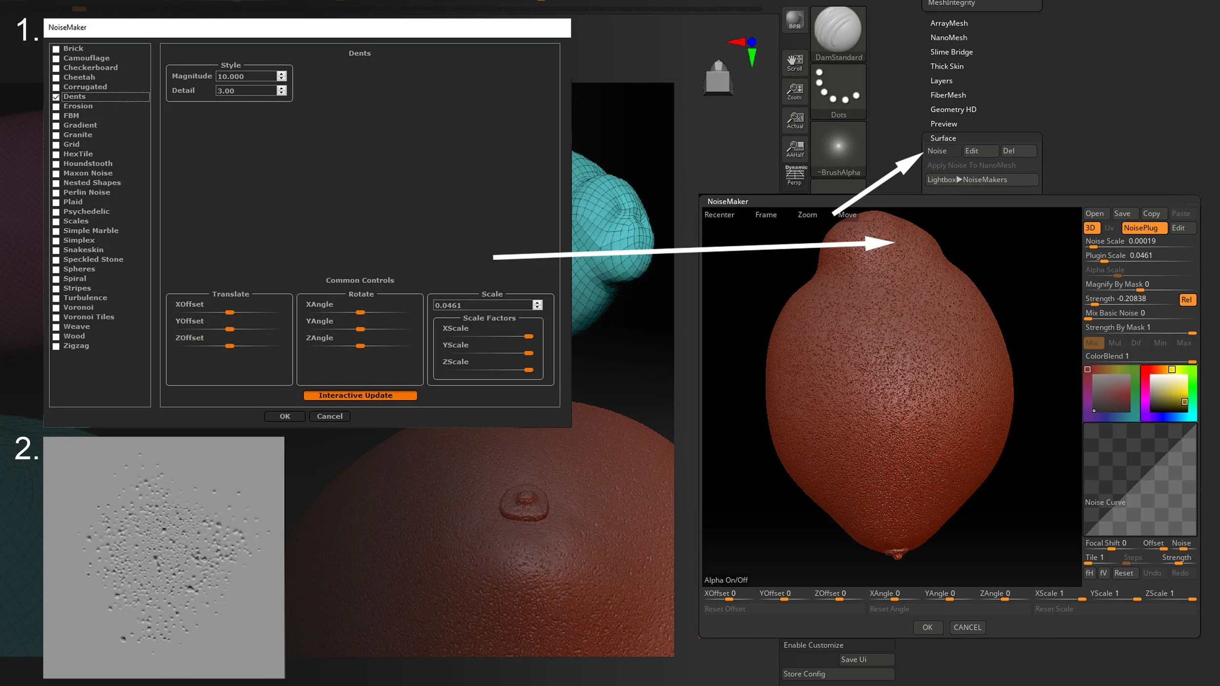
Fig 2.31 Noisemaker settings for lemon pores adding surface variations.
I would like to reiterate that the NoiseMaker is used to create a quick wash of noise. Once that is dialed in, I apply the noise to the mesh. With a few applications of polish lemon is ready for some final detailing from my lemon pores VDM Brush.
Please refer to the end of Chapter 2 for arranging the scene for yours sculpted items.